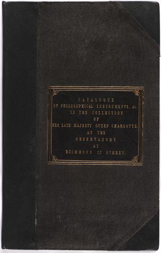
Manuscript entitled: "Catalogue of the Apparatus of Philosophical Instruments, in the Collection of Her Late Majesty Queen Charlotte, at the Observatory at Richmond in Surrey"

Catalogue of Useful Inventions for Cotton Spinners, Manufacturers and for all textile trades
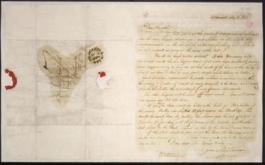
Letter from George Stephenson, Newcastle to Timothy Hackworth, Darlington
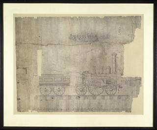
Drawing of St. Petersburg Railway Locomotive
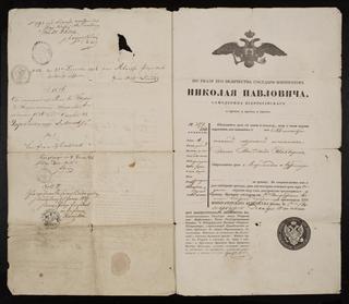
Passport

Working Drawing for No 124 Locomotive
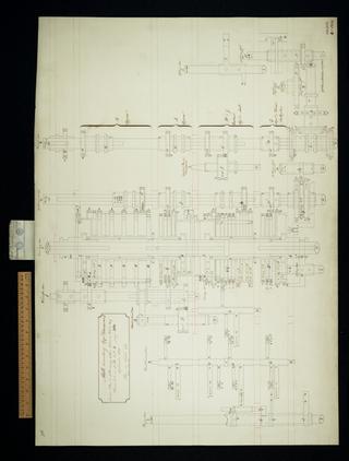
Mill counting apparatus. Consecutive elevation.
Working Drawing for No 136 Locomotive
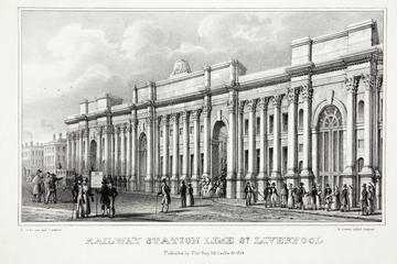
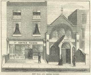
Lithograph of Lime Street railway station, Liverpool
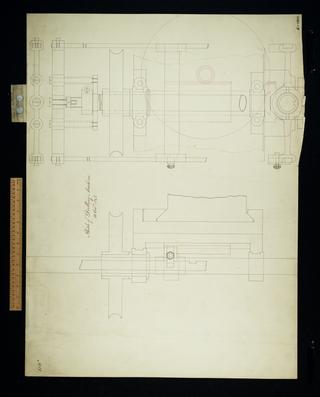
Sketch of drilling machine. Details.
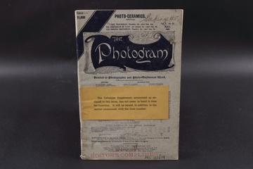
An edition of 'The Photogram' journal vol. 2 no. 17
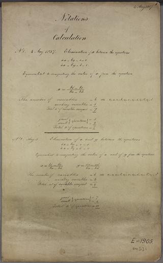
Solution of two simultaneous equations
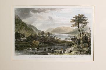
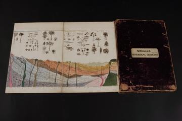
Engraving of 'Lake Thirlmere or Wythburn Water, Cumberland'
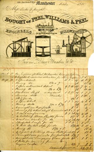
Invoice from Peel, Williams and Peel for a steam engine supplied to Messrs Coates and Wright

Working drawing for Nos 114, 115, 116
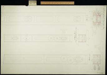
Figure 1. Plan, elevation and detail.
Railway Signal Volume 3 (1885)

Carriage and method of setting spiral axes for a machine of 50 cages with two figure wheels in each cage. Plan, elevation, details.
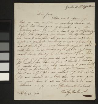
Letter from Timothy Hackworth, Guild Hall Coffee House to Jane Hackworth (nee Golightly), New Shildon

Working Drawing for No 149 (150 deleted)
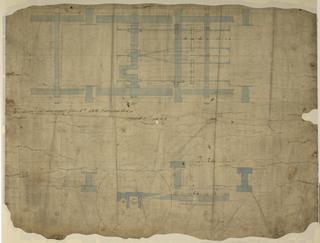
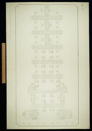
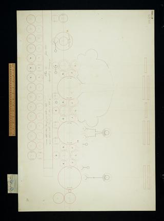
Plan of left half of middle group for General Plan 28.
Small planing machine. Sheet 1.

Addition and subtraction. Multiplication by stepping without table (to be done in store). Division by powers of ten (stepping done in store).
Plan of mill, table wheels and carriage. Sheet 31.
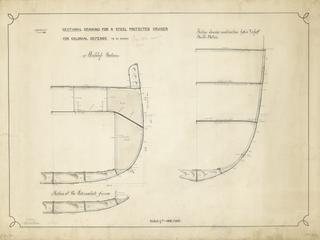
Drawing entitled 'Sectional Drawing for a Steel Protected Cruiser for Colonial Defence to be named'

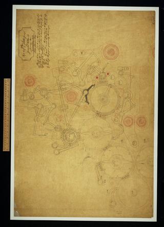
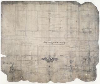
General plan of the Analytical Engine, half size.
Notation of the Analytical Engine

Plan 16. Arrangement, several partial arrangements, numerous notes.

Plan of operation and variable card counting apparatus. Suited to Plans 28 and 28a.
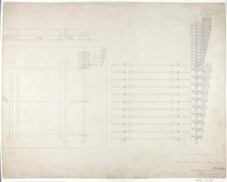
![Untitled. [Vertical positions of some of the wheels of Plan 28a. Notation 348 and 331 cycles]. Sheet 12 of 13.](https://coimages.sciencemuseumgroup.org.uk/221/221/large_thumbnail_bab_f_352_12_0001_vertical_positions_of_some_of_the_wheels_of_plan_28a_1845_oct.jpg)
Untitled. [Vertical positions of some of the wheels of Plan 28a. Notation 348 and 331 cycles]. Sheet 12 of 13.
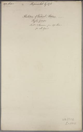
Skeleton of vertical motions for all operations. Right groups. Multiplication and division from 372 Sheet 1. Sheet 1 of 3.
Working Drawing for No 164

Gearing et cetera of Sketch dated July 31 1835. Plan, once part of Drawing 22.

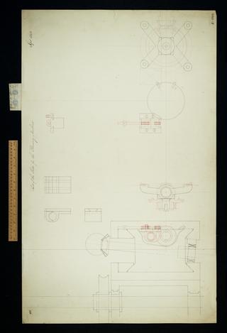
Parts of slide for the Planing machine. Plan, elevation
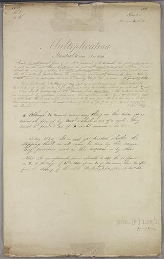
Multiplication. Sheet 1 of 4.
Algebraic addition. Sheet 1 of 2.
Difference Engine index of parts.
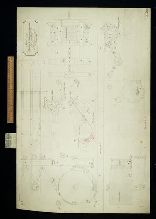
Sketches of the printing and stereotyping apparatus of the Analytical and Difference Engines. Superseded. Plan, elevation.

See designs dated 1834 November 27 and 1834 December 29.

First sketch of all the parts in plan of the right half to middle group of General Plan 28. Plan, elevation.

Parts of the slide for Planing machine. Plan, elevation.

Notation of periods for the centre group.
Plan 27. This was superseded by Drawing 93. Linear arrangement.

Plan and elevation of sundry parts in the upper cages of left half of middle group.
Parts of the slide for the Planing machine.
Algebraic addition of i k figures. Sheet 4 of 8.
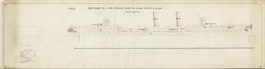
Drawing entitled 'Sheer Drawing for a Steel Protected Crusier for Colonial Defence to be named'
Multiplication before the invention of multiplication by table. Sheet 2 of 2.